Monday, October 24, 2011

Frantic Prep

August 18-22, 2011


Certification Loomed on the horizon the way a cold front plows up a bank of thunderheads in the distance; no escape but to push headlong into it. With the Safety and E-test check booked for the 23rd, I gave the beast a pretty thorough inspection and whipped up a short list of things I would need to complete over the next couple of days.


I street legalized all the Bondo work and got most of the bare steel painted for the trip north (should I get that far), as well as reinstalling any trim that needed to go back on. I pillaged the old TJ bumper from storage and welded up a few quick mounts to hold it in place as a temporary bumper while my real one was being fabricated.


An electrical check revealed my rear side marker signals didn’t work; with the multimeter reading about 2 volts instead of the required 12. Without the time to do proper continuity tests to find where 10 volts either escaped or couldn’t pass through a bad connection, I rigged up a splice to piggyback the power off the more robust tail light signal circuit. It meant they didn’t alternate blinking but it meant they now were legal.
 

On the evening of the 22nd, about 16 hours before my test was booked, I took the vehicle for a quick spin to warm it up past driveway idle; with the intent of finding any weak points that otherwise wouldn’t appear until a road test.


The test worked.

When the power steering fluid began warming up, the pressure in the steering system increased to reach its normal operating temp/pressure. This caused a small pinhole leak in the low pressure line to begin dripping in a fairly constant 1 drip per second pattern. I reached in and gave the steel line (where it exits the box) a slight wiggle and it ruptured; bleeding itself out all over the garage floor like a mortally wounded Buck. Seeing as how it was passed closing time of Canadian Tire, I proceeded to dismantle the low pressure side of the system and took stock of what I needed.


In the morning, I slipped over to CT early to get the best start on my day. At T-6:00 I was told they didn’t stock parts for the Saginaw Steering system, the box that lived under just about every 4wd truck pre-1994 (and possibly after). Since I had the piece with me the Desk-Guy and I went to their fuel and brake fitting section and paired up a nearly identical match to the old fitting. I didn’t care that the line was intended for a GM sending unit, it bolted right up and I had steering in under an hour after purchase. I refit with new hose, clamps, and o-rings and then topped up the fluid. A few last minute dustings made it look semi-presentable before my brother in law came to pick it up for its appointment.


Friday, October 21, 2011

Big Booth

August 13, 2011

Manhandling a driver door into a small paint shop is easy; manhandling 4 doors, a hood, fenders, and a grille into a paint booth requires more space (still not hard), but fitting a 16' long truck into the same booth can be a sizeable task. Throwing a 19'x10' airtight structure together in a couple days requires that most of the work already be done for you.

Enter the Barn, Circa 1900. This building has an extended threshing floor for extra space, and solid 2.5" thick floors on Hemlock Beams. Bracing, Posts, and Swing Beams make for perfect backing components; just build the booth indoors. I began with a full bundle of assorted wood left over from church production props (Adventure to Bethlehem no less)


In Brief, the structure used a rib-like design that can later be collapsed and stored in pieces so i can use it again. It has a peaked roof, Garage style flip front door, and proper ventilation. The floor is sealed with large layered lumber tarps, and the walls are medium (about 8mil) vapour barrier. the man door is sealed by leaving a flange of vapour barrier around the perimeter that is trapped when it closes. a rear evacuation system uses an auxiliary fan from a 1990 Ford Taurus, sucking through 3 furnace filters (medium duty) the intake vents at the front are up higher than the rear exhaust, this causes the vapours and overspray to be sucked downwards.


Update from Early September. I left the vapour barrier until i needed it, this way it was dust free.


 Sneak peek

Tuesday, October 18, 2011

Late July – Early August 2011
Having booked myself in at the local Subaru Garage for a safety test and an e-test, it was time to tie up the remaining loose ends and get the vehicle into a passable condition. For the Wagon this meant mostly doing some more realistic Bondo prep and sanding; not to mention spraying those panels with primer to cover the bare steel.
In Typical More-than-I-bargained-for fashion, the Bondo was taking more time than I would have cared to allot to it in the first place, but since the clock was winding down I had to press on regardless of how long it was taking me (might have aided myself to have used some better bodywork tools; a long Lowes paint stick was the backing for all my sanding, allowing me to get the curves more or less right.


By the time I was more or less happy with the bodywork (aside from spot putty and final sanding) I shot some red oxide primer on it to keep whatever rust that wanted to form away from it. I also finished up the CAD for the Front Bumper I have been proposing all these years. I got in touch with a local metal fabricating shop that I’ve been in contact with for a few years (dare I plug them here?) called Templeton and Sons here in the GTA. These guys do excellent work and they are very reasonable in terms of their pricing (a full custom bumper turned out to be roughly the same if not cheaper than an OEM replacement). They do laser cutting, cnc press bending, and are fully certified to weld all sorts of metals. I will in the short term get a rear bumper done there of the same design persuasion.

Thursday, September 22, 2011

Sit-Rep: Tach & Antennae

July 22 (ish), 2011

This is pretty brief, but it comes in the form of a micro-rant. I hate it when car companies think that since the vehicle is automatic the driver has no regard for what the engine is doing, so they don't bother installing a tach to save space or something. This is even more prevalent in a stickshift (such as my Echo, which is standard, and has no tach... I suppose they want me to just guess?)

Because of this manufacturing gaffe, I bought an inexpensive tach for the echo years ago, but it turned out to be incompatible with the more sophisticated (though I typically like sophistication in a lot of things) ignition system. I therefore shelved it for a few years until I got around to installing it in the more archaic 70's bred Wagoneer ignition system (which as legend has it was cobbled from Ford).

This was just about as easy as that staples button. A quick self tapping screw holds the mount against the A pillar, and the wiring tucks neatly doen the side of the dash behind the weatherstripping. It then runs through the firewall to it's respective coil mount.


Next came the relocation of the radio antennae. This was also fairly easy, using a shortened section of the cable routed behind the passenger side dash (which is a completely empty cavern I might add, tucked behind the original 1963 dash steel that Jeep neve bothered to change). There is a 1/2" hole at the end of the dash where I fished the cable through, and turned it up to plug into the original exterior mount. Then I essentially just jammed it in place, with the provision that I would later secure it somehow. Note; this requires you to either cut your antennae down to about 16" or use an off the shelf shortened one. I had some of these yellow ones laying around in new packages, so I popped one open and it slotted in as a perfect fit. Now my 1 speaker radio has some matching receiver action to boot.


Saturday, August 6, 2011

Re:Mounts

June 18, 2011

Probably a good idea when looking at an old "body on frame" vehicle to give the body mounts a good forceful tug. Had I tugged mine earlier I would have caught both the 2 front body mounts, as they were only held in place by the rubber that comprises them. The bolts inside had rusted through completely, and swelled in true cauliflower style so that the once 3/8" collared bolt was now an inch around due to puckering, and was completely severed from the rest of the body. I noticed the mount itself is fairly badly rusted as well... shhhh.


I was able to cut into the floor above the mount, where a special housing held a blind nut with the remaining stud still in it. Since I could not drill this out my only option was to shear it clean from the frame rail. A little bit of punch work and some wiggling freed up the old crumbled mess of the bolt. This allowed me a clear shot through the old bodymount with a new stainless (304) bolt, with large fender washers and flange nuts.


I  Fed the whole deal back together and repeated the process on the drivers side (wish i'd noticed this before doing my floor repair initially.

Tuesday, May 10, 2011

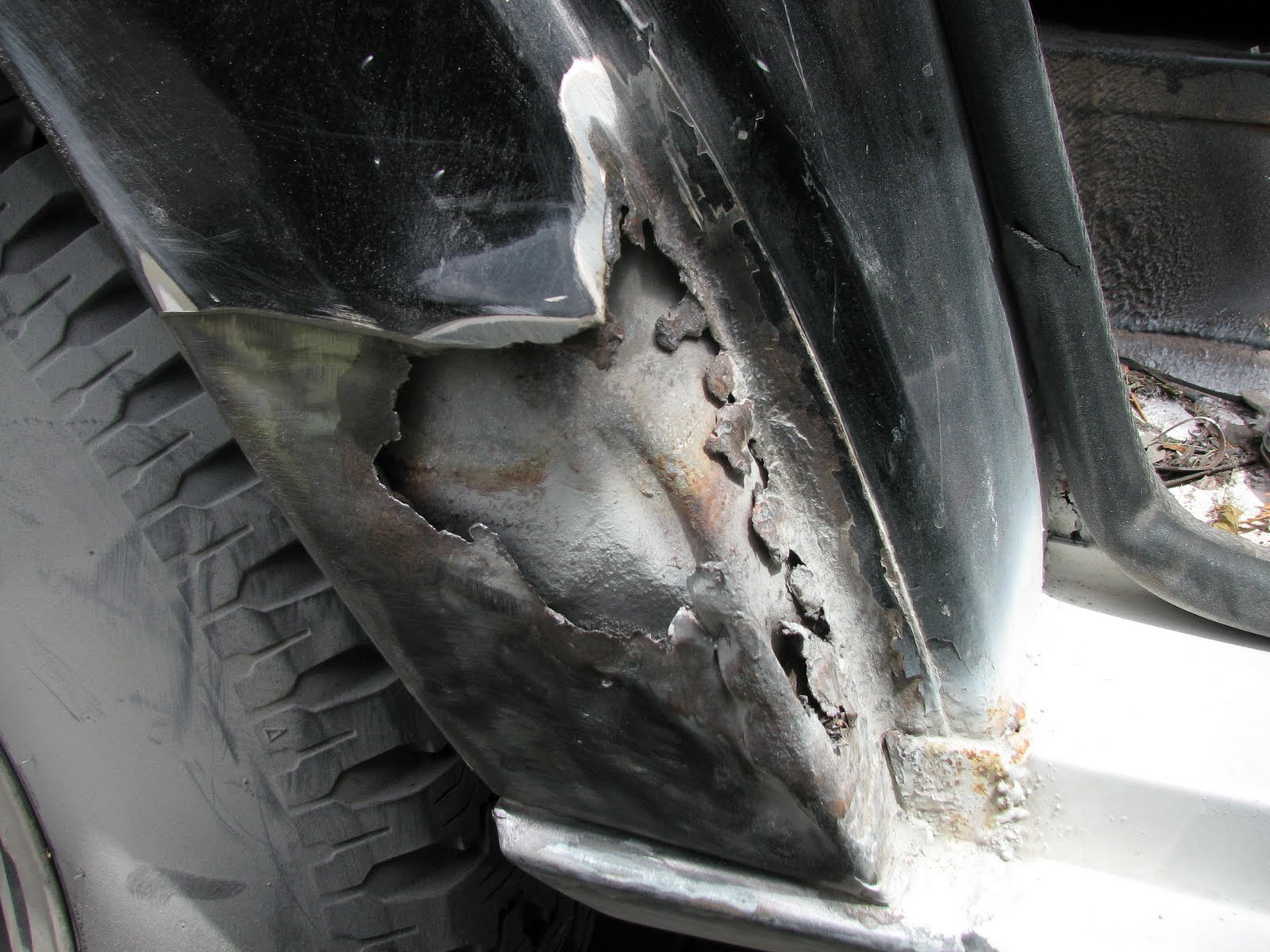
Oh Look; More Rust


May 7, 2011
 
It seems that rather predictably, someone in the past indulged their insatiable craving for hitting something and then smearing on as much Bondo as their silicone spatula would allow. 


To placate the rig’s gaping wound, I mapped out a plan to patch in some new steel and give the beast some much needed rigidity. This began with some rudimentary sharpie work, and some exploratory wire-brushing to remove a few pounds of bondo. The rather extensive rust had eaten its way through most of the lower “dog leg” section, and by the looks of things, someone had done some brazing work with some new steel years ago. I grabbed the grinder and cutoff wheel and plunged into the body, slicing back until I was able to find good thick steel. 


This angular cutout then served as the template for my new steel patch, which I decided to tackle in 2 stages; the first part being the return portion that runs back into the door opening, and the second being the visible portion of the dogleg. I regret now not treating that rust on the inner steel of the wheelwell, and will likely have to tackle that in the future. 

After mocking up the patches using thick cardstock, I duplicated the patch out of either 18 or 20 gauge steel (not sure which). I learned years ago on another patch that it is best to curve the steel around a corner instead of welding right at the corner, as it makes for a cleaner bodyline that you can use when filling. Nipping the edge into little tabs allowed me to do the required compound curves on the steel to achieve the closest match I could to original.


With the first patch in place, I focussed my attention on getting the second, more visible patch in. doing the patches in this order ensured I would get the correct bodyline from the previous patch. I made the patch slightly oversized and trimmed it for an exact fit. By tack welding the bottom in first, I was able to progressively line up the patch and tack it in, finally using a body hammer and a dolly to achieve the small angular bodyline at the top (which was difficult to replicate). Some filler should bring the correct lines back, as the rest of this small panel had been damaged and repaired before. 


Monday, April 25, 2011

Plans, Plans, Plans

In a somewhat artistic fashion, I am breaking code with my "chronological order" of things today. Since I haven't worked on the Wagoneer all winter (accounting for the lack of posting), I have devised a sketch in the warmth of my studio. I never really planned out what I wanted to accomplish with this project until quite a while into owning it, possibly because the amount of work was so foreboding that I wasnt able to get my mind past it. 

Now that all my mechanical work is complete (thanks to several days of holiday; and the subject of a subsequent blog), I am able to more or less visualize what I want the Wagon to end up being. First of all, no more woodgrain; this took only a few clicks of the mouse on the net to discover that replacement woodgrain is worth about 4 times what I paid for the truck in the first place, and I can put that money to better use.

One of the nice things about sketching is you can mock up any design you want, whenever you want. Not to sound nostalgic but I still prefer good old fashioned hand drawing over CAD programs or photo manipulating tools; it's typically faster anyways.

This overlay sketch (uses many sketches as underlays to develop the final image) is a rough depiction of my concept for the finished product, using a blend of new custom designed equipment while retaining the rugged mid 60's looks. the stripe (in vynil) denotes the engine displacement instead of using the cliched "V8" emblem, tones which are picked up by the dual exhaust and glasspack mufflers. Thinking of badging it the "Timberline" to denote the sort of rugged landscape this vehicle is built for (like the term "treeline," the timberline is typically the elevation where trees become sizeable enough to be used commercially). 

The utility rack is designed to fit the stock roof rack mounts, while following the contour of the roof and deflecting wind to hopefully aid a bit in aerodynamics; as if it mattered. Front and rear utility bumpers freshen the face from the tired sculpted aluminum ones that made it look so dated. They give it a more muscular appeal, and are far more useful than the original, integrating tow hooks, trailer hitch, winch mount points, and heavier protection.

Although the sketch is along the lines of a 4-6" lift, I will be going for something more like 2" for better road manners, and cost effectiveness. the tires are merely conceptual, but I will likely look for some aggressive tread meat once my stock tires wear out (they are currently brand new).

As an aside, I have never been a particular fan of that grille. I would like to swap in a mid 60's through mid 70's grille, as they are more durable and better looking.